Most of the information below is from a Rain Bird DV valve installation instruction pamphlet which is out of print. Some of the information below is from a newer, much smaller, and somewhat less informative flyer which replaced the larger pamphlet.
These instructions are generally quite good. In the interest of reproducing the instructions accurately, and so that we could attribute the source as being from Rain Bird, we have refrained from modifying them in any way (except for fixing a couple of their spelling errors and probably adding a couple of typos of our own!) The only way in which our opinion deviates from the advice below is that we recommend either multi-strand or solid wire (not just multi-strand) and we generally discourage manifolding valves, ESPECIALLY above ground! Also, it's not necessary to buy the specific Rain Bird water tight connector mentioned- there are several good ones available.
Those details (mentioned above) that we take issue with are pretty specific, and are only a small part of what's covered below. In general, you would be well served to read these instructions thoroughly when installing ANY brand of valve, although the appearance and features of other valves will vary somewhat.
Rain Bird DV Valve Instructions
 |
|
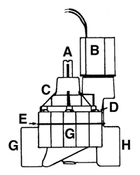
Parts include:
A = flow control stem
B = solenoid
C = bonnet
D = bonnet screws (6)
E = diaphragm location
F = body
G = inlet
H = outlet
Parts not shown:
Solenoid handle (at B)
Flow control handle (at A)
|
General Information
The DV series of valves offer an array of products in both sizes and features to meet the standard installation needs for residential and light commercial irrigation requirements.
- The valves offered are a 3/4" (20/27) non flow control valve and a series of 1" 26/34) valves with or without flow control and threaded or slip x slip configurations on the inlet and outlet ports. The combination of forms available offers maximum versatility to the installing contractor.
- The 3/4" valve should be used on laterals with flow rates from 3 to 22 GPM (0,75 to 5,0 cubic meters/hr or 11,4 to 83,4 L/m) or may be used on a drip master valve set-up with an RBY-075-200MX filter at flow rates as low as 0.2 GPM (0,5 cubic meters/hr or 0,8 L/m).
- The 1" valve series may be used on laterals with flows of 3 to 40 GPM (0,75 to 10 cubic meters/h or 11,4 to 151,6 L/m).
- In either 3/4" or 1" size, it is recommended that velocities be kept below 5.5 ft/sec (1,68 m/sec). DV valves will perform in an operating range of 15 to 150 psi (1 to 10 bars or 100 to 1,000 kPa).
Tips on Installation
- Adequately flush the main water source prior to plumbing in the valves.
Valves are not backflow prevention devices. You will need to install the appropriate device as mandated by local ordinance prior to the installation of the irrigation valve. Ensure that the selected device offers adequate flow and pressure to the downstream portion of the system to operate the sprinklers.
- Local practice may also dictate the installation of a master valve or isolation shut-off valve prior to installation of a DV valve. This will be very useful in shutting down a portion of the irrigation system without affecting the entire system.
- Check the electrical specifications of the controller being installed on the job to ensure that you have adequate inrush and holding current to electrically activate the valves. This is particularly important if you plan to wire more than one valve to a controller station. The DV solenoid is rated at 0.30 A, 24 VAC (7,2 VA) inrush and 0.19 A and 24 VAC (4,6 VA) holding current to maintain activation of the solenoid for the scheduled run time. Except for the EZ-1, all Rain Bird controllers will allow you to run two valves plus a master valve at one time. The EZ-1 allows one valve plus a master or two valves without a master valve.
- Local practice will dictate the standard installation procedures. However, it is always recommended that valves be installed in a valve box to allow access if servicing is required. This process will also allow easier identification of where the valves are actually installed on the job site.
 |
Installation Steps
- Adequately flush the main water source prior to plumbing in the valves.
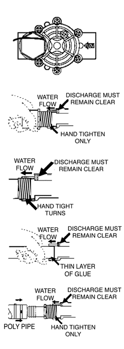
- Notice the directional arrows on the inlet and outlet ports which indicate the flow path of the water. Valves cannot be reversed. Ensure that you are installing the valve correctly. As a hint, you will find that the solenoid is always positioned on the downstream side of the valve where the water will be exiting to serve the sprinklers.
- The standard 3/4" and 1" DV comes with female threads. Use a 3/4" or 1" male by slip adapter to connect the valve to the water source. Use two wraps of Teflon® tape on the adapters and screw them into the water ports of the valve. Finger tighten into position and then turn one or two additional turns using a wrench to ensure water tight connections.
- Do not overtighten the adapter, or you could force the adapter to extrude over the solenoid exit port. the valve will not activate in this condition, Once properly attached, glue the slip portion of the adapter into the supply side pipe. Complete this step for all valves on a given master or isolation valve.
- The DV SxS valve eliminates the need for the adapter. In this case, simply glue the pipe into the two water ports of the valve. Use only minimal primer and glue to eliminate possible contamination of the valve ports from glue residue.
- In cold weather climates, it is more common to use poly pipe. Use appropriate installation techniques as specified by the manufacturer to properly attach and secure the poly adapter to the valve. Local practice will dictate the number of clamps used to secure the adapter.
- Slowly charge the water supply system to the installed valves. When the water first enters the system, the valves will open until the upper diaphragm chamber charges and shuts down the valve.
|
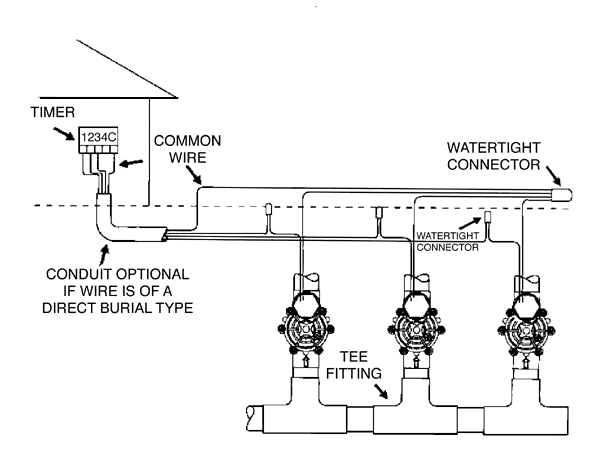
Wiring the Valve (See figure above.)
The DV valve comes with two lead wires, both black. Either one may be used as the common or as the hot wire back to the controller.
- Select a wire gauge which will allow you to run back to the controller with minimal loss (click here for wire size table). Most often, multi-strand direct burial wire will be preferable.
- All valves going back to the controller can utilize the same common wire. If the valves are manifolded, simply wire the valves together using water tight connectors and run one common wire back to the controller. If the valves are separated, run one common line and splice it to the remote valve common at each location.
- Each individual station must be wired separately to activate. Select a wire color and use a water tight electrical connector to wire the valve back to the controller. This wire runs directly from the valve back to the controller and is not ganged with any other wires. The use of Rain Bird ST-03 Waterproof connectors are recommended for all water tight connections.
- Hook up all wires back into the controller by positioning a hot wire for each valve onto a controller terminal strip and connecting all the commons back to the correct position on the controller.
Determining Valve Wire Sizes
- Determine actual distance, along wire run, from controller out to the first valve on a circuit and between each succeding valve on a multiple valve circuit (as shown in the figure below).
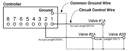
- Calculate the equivalent circuit length for each valve circuit on the controller.
Example: Solenoid elec. control valves with 24 VAC transformer controllers, with 150 psi water pressure at valves.
Equivalent Length Calculations:
Station #1- Equivalent Length = 1 valve x 200 ft. = 200 ft.
Station #2- Equivalent Length = (1 valve x 100 ft.) + (2 valves x 300 ft.) = 700 ft.
- Selecting Common Ground Wire Size- Using longest equivalent length calculated above, go to the appropriate valve chart (based on transformer voltage, 24 VAC, and water pressure at valve) and select ground wire and control wire combination that are as near the same size as possible (ground wire size should always be equal to- or one size larger than, the control wire size.
In the example above, circuit #2 has the longest equivalent length of 700 feet. In chart (for this example use high pressure chart for 150 psi water pressure at valve and 24 VAC transformer) select a wire size combination of size 16 and 18 wire. Select common ground wire as size 16 wire. Since one common ground wire shall be used for all valves on the controller, you have established the common ground wire size for that controller of size 16 wire.
- Sizing Circuit Wires- Using the common ground wire selected (size #16)- proceed to select each control wire size, from the chart, using the calculated equivalent length for each circuit.
Station #1- Equivalent Length = 1 valve x 200 ft. = 200 ft.
Select size #18 control wire.
Station #2- Equivalent Length = 1 valve x 700 ft. = 700 ft.
Select size #18 control wire.
 |
Manually Activating the System
The DV valve series offers two ways of manually activating the system.
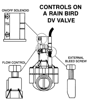
- The solenoid allows manual activation of the system with internal downstream bleed. Utilizing this method will eliminate water in the valve box. On the side of the solenoid, arrows indicate the on and off position. You need turn only 1/4 turn CCW to manually activate the valve using the solenoid. Since the solenoid seat is subject to system pressure, it may be difficult to turn in jigh pressure situations. Turn 1/4 turn CW to close the valve after flushing.
- The external bleed screw offers an alternative manual option. Because it is assisted by the pressure of the system, it may be easier to engage than the solenoid under high pressures. It is located on top of the bonnet assembly and may be turned to activate the valve. You will only need to turn it one turn before water starts to exit the valve directly below the bleed screw. Do not turn any further as the screw is not captive and may come out.
|
- Use the external bleed screw to flush the valve prior to electrically activating it. Continue piping the system until completion of the valve installation. Activate the valves electrically from the controller to ensure proper functioning.
|
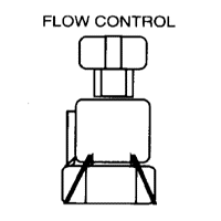 |
Flow Control Stem
The flow control stem allows you to reduce valve output pressure by turning down the stem until the desired effect is seen in the sprinkler operation. You may turn the handle with your fingers or use a slotted screwdriver. |
 |
Filters
The DV series has two filters in the water flow path to reduce plugging of the valve ports.
- One filter is on the diaphragm to filter the upper chamber water supply. Do not remove the diaphragm filter because the valve will not operate. The other filter is in the solenoid to prevent plugging of the solenoid ports and to keep debris off the plunger if the solenoid is removed. Both filters are sized to allow the proper flow of water to achieve the desired hydraulic effects.
|
Winterization
As with all irrigation components, it is important to properly winterize the valves prior to the first hard freeze. Local practices will dictate how this is done, but blowing the system generally provides the best protection. Failure to properly winterize may result in damage to the valves as water captured in the valve freezes.
- Compressed air source should not exceed 60 psi.
- Upon completion of the winterization process, move the controller to the stand-by mode.
| If you've benefited from the help we've provided on our site but you choose not to purchase your parts from us, we hope you will consider making a small donation to help offset the cost of maintaining this site. To make a donation, you can click on a button below and follow the on-screen instructions. |
|
|
|
|
Thanks!
The staff at WaterTips.com |
|


